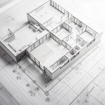
How to Read and Understand Architectural Drawings
Architectural drawings are the blueprint of every construction project. Whether you’re planning a home extension, a new build, or a larger development, understanding these drawings helps you make informed decisions and avoid costly misunderstandings.
For many homeowners and property developers, architectural plans can appear complex and technical. However, once you understand the basics, reading drawings becomes much easier.
At Buildrite, we ensure our clients fully understand their architectural drawings before construction begins, providing clarity, transparency, and confidence at every stage of the project.
What Are Architectural Drawings?
Architectural drawings are detailed technical representations of a building. They communicate design intent, dimensions, materials, and construction requirements to builders, engineers, and planning authorities.
They serve several important purposes:
- Visualising the design
- Securing planning permission
- Meeting building regulations
- Guiding construction teams
- Preventing design errors
Understanding these drawings ensures everyone involved works from the same plan.
Types of Architectural Drawings
Before learning how to read them, it’s important to understand the different types of drawings typically included in a set.
1. Floor Plans
Floor plans are horizontal views of a building, as if you are looking down from above with the roof removed.
They show:
- Room layouts
- Wall positions
- Doors and windows
- Staircases
- Dimensions
- Furniture layouts (sometimes)
Floor plans help you understand how spaces connect and flow within the building.
Buildrite ensures floor plans are clear, practical, and optimised for functionality and compliance.
2. Elevations
Elevations show the exterior view of a building from each side (front, rear, and sides). They indicate:
- External appearance
- Window and door placement
- Roof design
- External materials
- Building height
Elevations are essential for planning approval because they show how the building fits within its surroundings.
3. Sections
Sections are vertical cut-through drawings that reveal internal details of the structure. They show:
- Floor-to-ceiling heights
- Roof structure
- Foundations
- Insulation layers
- Structural elements
Sections are particularly important for building regulation approval and construction accuracy.
4. Site Plans
Site plans show the building’s position within the plot of land. They include:
- Property boundaries
- Driveways and access points
- Landscaping
- Nearby buildings
- Orientation (north point)
Local planning authorities use site plans to assess impact on neighbouring properties and compliance with zoning laws.
Understanding Drawing Scales
Architectural drawings are created to scale, meaning they represent real-life measurements proportionally. Common scales include:
- 1:100 (1cm on paper equals 1m in real life)
- 1:50 (used for more detailed layouts)
- 1:20 or 1:10 (used for construction details)
Understanding scale helps you interpret dimensions accurately.
Buildrite provides clearly labelled drawings with dimensions included to prevent confusion.
Common Symbols and Annotations
Architectural drawings use symbols to communicate information efficiently. Some common examples include:
- Door swing arcs (showing opening direction)
- Window markers
- Stair arrows (indicating direction of travel)
- Section markers
- Level markers (showing floor heights)
- Material hatch patterns
Annotations and notes provide additional clarification about materials, finishes, and construction methods.
Buildrite ensures all drawings include clear labelling and explanatory notes to make them easy to understand.
Reading Dimensions Correctly
Dimensions are critical in architectural drawings. They are typically displayed in millimetres in the UK.
For example:
- 3000mm = 3 metres
- 900mm = standard door width (approx.)
Always refer to written dimensions rather than measuring directly from printed drawings, as print scaling can vary.
Buildrite includes accurate dimensioning to ensure builders follow precise specifications.
Understanding Levels and Heights
Drawings often include level references such as:
- Finished Floor Level (FFL)
- Existing Ground Level (EGL)
- Proposed Ground Level (PGL)
These markers show vertical positioning and are essential for drainage, structural stability, and compliance.
How Architectural Drawings Are Used During Construction
Once planning permission and building regulations approval are granted, architectural drawings guide the construction team. Builders rely on:
- Layout dimensions
- Structural details
- Material specifications
- Elevation references
Misunderstanding drawings can lead to construction errors, delays, and additional costs. That’s why clear communication is essential.
Buildrite supports clients throughout the process, ensuring drawings are fully explained before construction begins.
Why Understanding Your Drawings Matters
When clients understand their architectural drawings, they can:
- Confidently approve designs
- Request informed adjustments
- Avoid unexpected surprises
- Ensure the final build matches expectations
Architectural drawings are not just technical documents — they are a roadmap to your finished project.
How Buildrite Helps Clients Understand Architectural Drawings
At Buildrite, we believe clarity is just as important as design quality. We provide:
✔ Detailed and easy-to-read architectural plans
✔ Clear dimensioning and labelling
✔ Step-by-step explanation of drawings
✔ Professional guidance through planning approval
✔ Ongoing support during construction
Our goal is to ensure clients feel confident and informed at every stage of their project.
Whether you are planning a small extension or a large development, Buildrite simplifies complex technical information into clear, actionable plans.
Common Mistakes When Interpreting Drawings
Some common misunderstandings include:
- Ignoring scale
- Misreading dimensions
- Overlooking section details
- Focusing only on floor plans without reviewing elevations
- Not clarifying unclear notes
Professional review and explanation prevent these costly errors.
Conclusion
Architectural drawings may appear technical at first glance, but understanding the basics makes them far more approachable. By learning how to read floor plans, elevations, sections, and site layouts, you gain greater control and confidence over your building project.
Clear, accurate drawings are the foundation of successful construction. With Buildrite’s expertise, clients receive not only professionally prepared architectural drawings but also clear explanations and guidance to ensure complete understanding.
If you are planning a project and want expert support in navigating architectural drawings, Buildrite is here to help you move forward with clarity and confidence.